

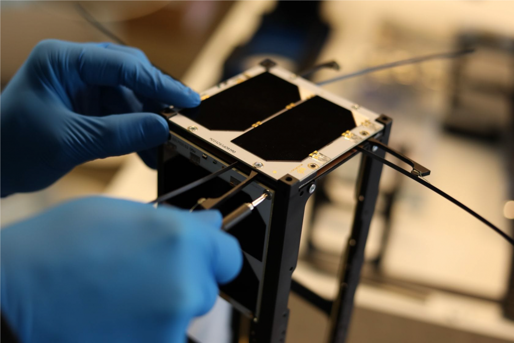
PHOBOS CUBESAT PROJECT
We will take high-resolution 1 cm (0.4 in) / pixel images of Mars's moon Phobos.
We will take high-resolution 5 cm (2 in) / pixel images of Earth's moon.
Please support this project to make it all happen.
Phobos CubeSat project details
Phobos CubeSat project details.
Overview
Our project aims to send a small Cube Satellite to the Mars’s moon Phobos and Earth’s moon and take High-Resolution pictures from low orbit. We chose to use COTS (commercial off-the-shelf) product to build our CubeSat to cut the cost. As the cost to get to the Moon’s orbit is still too high, we decided to pack more fuel and get there slowly from LEO.
Our planned launch date is the second half of 2025.
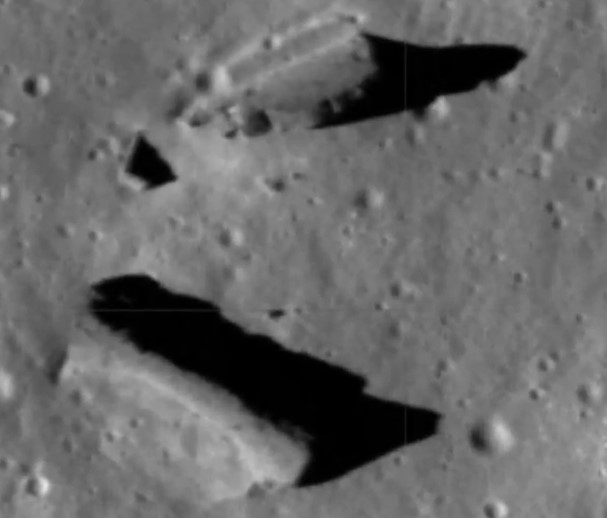
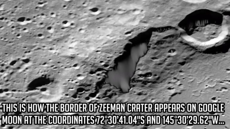
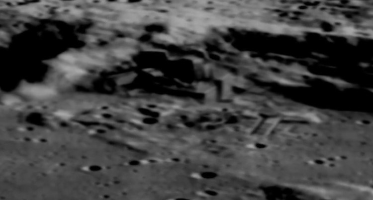
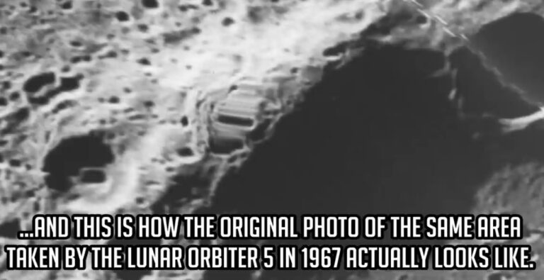
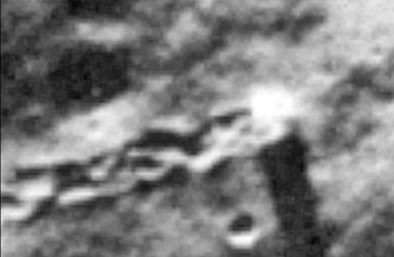
We have seen many pictures from the Moon, but it usually takes a long time to access them. There are also groups of people who think that some look altered, modified or even completely hidden from us. They believe that the organizations who take these pictures change some of them because of the infamous Brookings Report or other agendas. On the other hand, the other group of people believe that there is nothing to it. They think that shadows or camera processing errors can explain everything. Who knows?
Our Cube Satellite should be welcomed and supported by everyone who wants to know the truth, regardless of what they think about the official public pictures or NASA and other space organizations. This is an open project that everyone can participate in. All data will be available in RAW format in real-time to everyone. Anyone will be able to ensure that there are no secrets, no delays and no modifications.
The CubeSat images will either confirm that there is nothing unusual on our Moon and Phobos, or confirm some alien presence there. Maybe we will capture unique alien structures in high resolution, or even aliens having some party there, who knows.
In any case, all of us will be able to see the highest resolution pictures of all questionable places, and we will be able to settle this controversy.
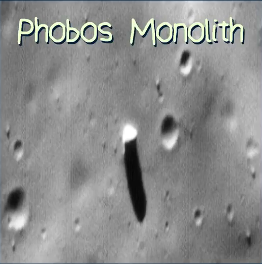
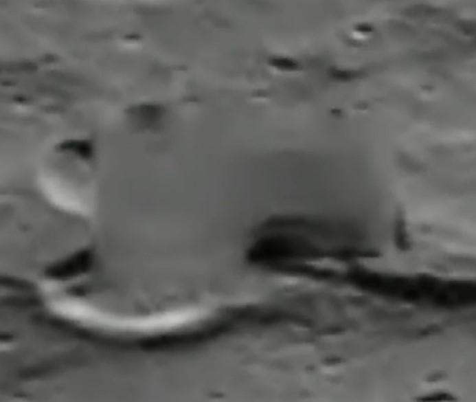
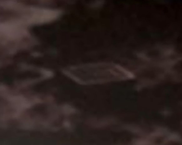
Some Interesting Anomalies.
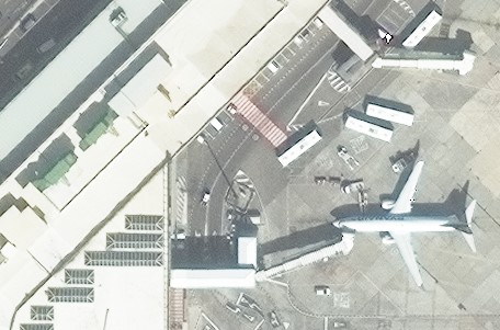
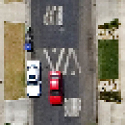
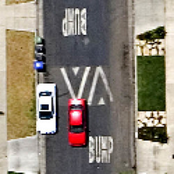
Spatial resolution
In any case, I think that if we all get together, we can finally find out the truth and resolve this controversy. We can get pictures of all strange objects on the far side of the Moon and on Phobos ourselves, without censorship and any alterations.
We will be able to orbit the Earth’s moon as close as 30 km from the surface and take Panchromatic pictures with a spatial resolution of around 30 cm (12 inches) / pixel. Or, with the optional camera, we can get a spatial resolution of an incredible 5 cm (2 inches) / pixel.
On Phobos, we will get a spatial resolution of around 1 cm (0.4 in) / pixel.
All the data will be immediately and freely available to everyone via the Internet. Every time we receive new data, we will announce it on Social media and Telegram.
This project is not about any country or individuals. It should be a project where all of us get involved, and all of us take credit.
I hope that we all get together and make it happen. We need as much input as we can from everyone. We would like you to join our team to make this project as good as we can.
If you:
- have any experience with CubeSats and like to help
- have any suggestions on how we can improve the project
- have any advice on what other equipment we should use
- have any suggestions on the best way to get from LEO to Moon’s orbit
- have any suggestions on what places we should take pictures of
Please get involved and contact us.
Join our forum on our website. https://forum.real-reset.com
More possibilities.
Some of our team members are also candidates to fly on the dearMoon mission, enabled by open-minded visionary, entrepreneur Elon Musk who is founder, CEO, and Chief Engineer at SpaceX and financed by Japanese billionaire Yusaku Maezawa. Wouldn’t it be great if the first private trip of EARTHLINGS around the Moon would take with them the first Cube Satellite with the capability to take pictures with up to 5 cm (2 in) resolution build jointly by EARTHLINGS volunteers? This resolution is about ten times higher than NASA’s Lunar Reconnaissance Orbiter. But then the CubeSat will fly to Mars’s Moon Phobos and take even higher resolution pictures of about 1 cm (0.4 in) there. Sound’s interesting, doesn’t it? Let’s hope that we can get enough support to make this project a reality.
If we get our CubeSat directly to the moon, we will have extra fuel on board to make many more orbital changes, as we will not use any propellant to fly from LEO to the Moon orbit.
Please join the Phobos CubeSat project on Indiegogo, and do not forget to spread the news on social media. Any donation, even $1, will help to make this project happen. We also welcome volunteers to join our team.
What is CubeSat
Components

Optional Upgrades
Some or all of these upgrades will be possible if we collect enough money over our target on INDIEGOGO campaign, or get some discount on our CubeSat’s equipment or delivery to the LEO or directly to the Moon.
Better Imager (Camera)
Spatial resolution on Moon ~ 14 cm (6 inches) for Panchromatic pictures.
Best Imager (Camera)
Spatial resolution on Moon ~ 5 cm (2 inches) for Panchromatic pictures
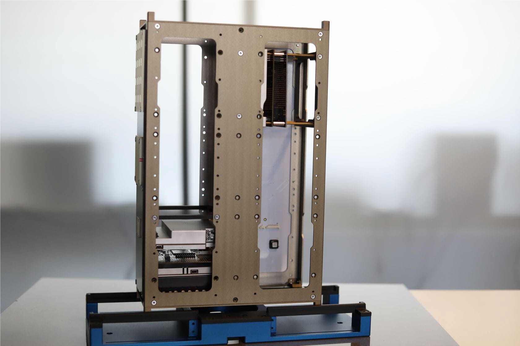
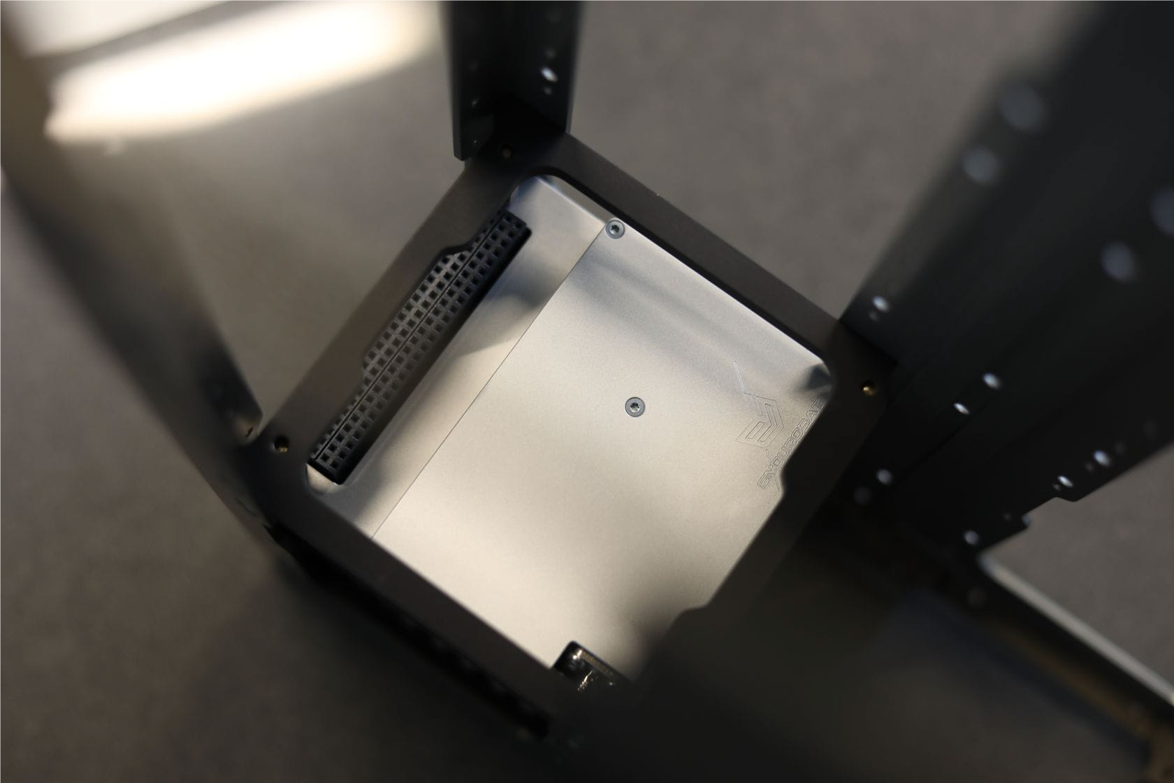
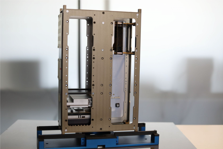
6U CubeSat Structure
The 6U Structure provides a simple and safe environment for payload as well as stable operational
ability of all subsystems during all phases of the mission. Compliant with CubeSat standard and compatible with a wide range of CubeSat subsystems producers, it allows for both vertical and horizontal assembly of modules through highly flexible interface sub-structures.
It come with kill switches and 2 separation springs already integrated (can be modified based on requirements).
Pearl finishing and hard anodization (30 μm).
- Dimensions: 100×226.3x366mm;
- Material: Aluminum 6082;
- Two kill switches option;
- Mass: ~ 1 kg (including bolts);
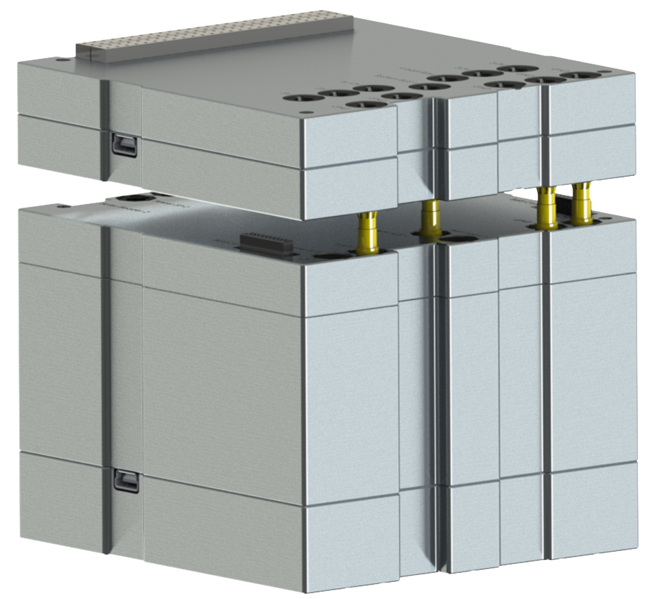
Electrical Power System (EPS) Type II + Battery Pack
The EPS Type II is optimized for large nanosatellites and microsatellites with high-power generation and handling requirements. It comes with integrated Li-Po battery packs encapsulated inside the aluminum box and the possibility of stacking additional battery packs.
The capacity of a regular battery pack is 84 Wh (8 cells). There are 3 + 3 Independent photovoltaic input channels with MPPT. Each channel consists of two connectors that are intended for opposite solar panels in order to maintain the input parameters within the maximum ratings of the module.
Highlighted features of the EPS:
- Input voltage (per Solar Panel Channel): 8 to 36 V
- Input current (per Solar Panel Channel): up to 4 A
- Stackable „Battery back “up to eight pack for max power up to 1 kW
- Integrated blocking ideal diode for each solar panel connector
- Output power buses: 2×3.3V, 2x5V, Programmable 1x12V (6-12V), one “Battery raw”
- Full redundancy of each BUSs
- Full protection (OV, OC, OP), current limitation up to 6A per channel and 8A of “Battery raw”
- System Bus voltage for 4 cells when charge state (configurable 17.8V-19.8V, by default 18.3V)
- 3.3V ,5V and 12V latch-up protected outputs
- Interfaces: RS485, USB (Virtual COM Port)
- Programable algorithm of charge and discharge and heater configuration
- Back-up bootloader and full redundant application software
- Full monitoring of each modules and preventing action for single event upset (SEU)
- Mass: 1350g (with large battery pack)

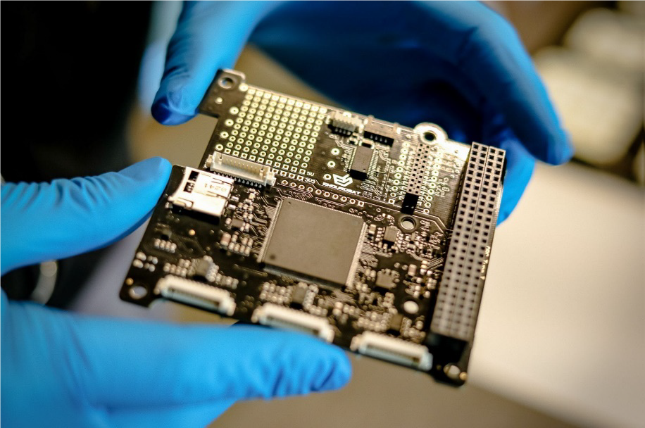
Onboard Computer
The onboard computer is a low power consumption and high-performance computing platform for nanosatellites, fully compatible with the CubeSat standard. It is based on ARM Cortex M4 with frequency rate up to 180MHz or optionally on ARM Cortex M7 processor with frequency rate up to 216 MHz. It comes with integrated double redundancy sensors: 3-Axis accelerometers and compass. PWM drivers for magnetorquers and inputs for sun sensors, temperature sensors and gyroscope allow the implementation of the attitude
determination and control systems. Product performance and properties:
- ARM Cortex M4/M7 processor;
- Frequency rate: up to 180 MHz for M4, up to 216 MHz for M7;
- 2MB Program Memory Size; 256kB RAM for M4, 2MB RAM for M7; 2048kB flash memory;
- MicroSD card slot;
- Integrated double redundancy sensors: 3-axis accelerometer and compass;
- 3x PWM drivers for magnetorquers;
- 6x analog inputs for sun sensor;
- 6x external temperature sensors can be connected;
- Interfaces: 2x USART, UART, 2x I2C, 2x SPI, USB Opt.;
- Real Time Clock
- Flexible frequency eco-mode;
- Mass: 58 g.
- 1Gbit Serial NOR Flash Memory
- Connector for antenna deployment
- Proto Board area for easy connection of payload and access to main power and communication busses.

6U Solar Panels and Deployable 3U Solar Arrays
Solar Panels utilize 7-20 CESI Solar cells CTJ30 with 29.5% efficiency per array. The wide effective cell area provides up to 1.2 Watt in LEO per cell. 3U deployable panels feature 7 cells on the deployable wing and 7 cells mounted on the wall. 6U deployable panels feature 20 cells on the deployable wing and up to 20 cells mounted on the wall.
On the PCB, a network of sensors (Gyroscope, Sun sensor, temperature sensor) and magnetorquer provide attitude determination and control system.
Single solar panel array features and characteristics:
- 7-20 CESI Solar Cells CTJ30, space qualified triple junction (specs in the following paragraph);
- Temperature Sensor with SPI Interface (Accuracy: ±1.5°C from -25°C to 85°C (max), ±2.0°C from -55°C to 125°C (max));
- Up to 1.2 Watt in LEO per cell;
- Gold plated invar interconnectors;
- Space-grade silicone adhesive with minimum outgassing behavior;
- Gyroscope;
- Sun Sensor;
- Multiple panels can be connected in series or parallel; Solar cell features and characteristic:
- Efficiency 29.5%;
- Triple Junction Solar Cells InGaP/GaAs/Ge;
- Polarity N on P;
- Very low solar cell mass (81-89 mg/cm2);
- Thickness 150 μm ±20 μm;
- Fully qualified under ESA Standard ECSS E ST20-08C for LEO and GEO;
- External By-pass diode for reverse bias protection;
- Size 30.15 cm2;
- High Radiation Resistance;
- Cover glass;

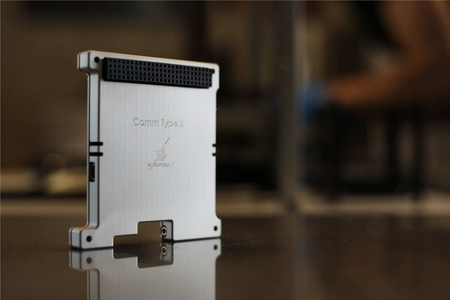
X-band Transmitter
X-Band Transmitter is a high data rate satellite module operating in the 8.025 – 8.4 GHz frequency band. This band is allocated by the ITU for Earth Exploration Satellite Services (EESS, Spaceto-Earth). The transmitter is designed to work in accordance with the DVB-S2 ETSI EN 302 307 standard. Other standards are also available upon request, for example CCSDS.
The form factor of the X-band Transmitter is built around the PC-104 connector standard which is the most common for CubeSat systems. The module has two modes of operation – Load mode and Transmit mode. In the Load mode the device is recording data into its internal memory (2x16GB) from the OBC or directly from a dedicated payload. It is intended for periods when the satellite is not communicating with the GS. Therefore, in this mode the module automatically switches off all unnecessary electronics and consumes less than 0.27 W. In
the Transmit mode the device sends the loaded data through the radio channel. The optimum output power is 32 dBm and can be regulated from 27 dBm to 33 dBm with a 1 dB step. The power consumption in Transmit mode with 32 dBm RF output power is 12 W. Four interfaces are available on the PC-104 connectors – I2C, CAN, UART and SPI. They are used for setting the communication parameters (e.g. operation mode, frequency, output power, symbol rate) and transferring the payload data. The RF output connector to the antenna is a 50 Ohm SMA female jack. The system has an easily accessible mini-USB connector primarily intended for setting
up the module and performing tests while on the ground.
The small overall dimensions of the metallic box combined with the robust HW architecture of the X-band
Transmitter makes it a perfect choice for CubeSat or nanosat missions.
- Frequency Range: 8025 – 8400 MHz;
- Maximum Transmit Power: 2W;
- Transmit data rate: up to 50Mbps;
- SFDR: > 60dBc;
- Power Supply: 12V;
- Power Consumption during Tx: up to 12W;
- Data Interface: LVDS, SPI, CAN, I2C;
- DVB-S2/S2X, CCSDS compliant;
- Mass: 270 g

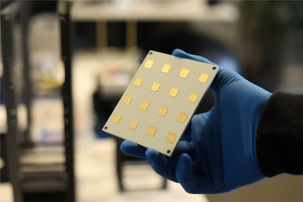
X-band Patch Array (4×4)
X-Band 16 Element Patch Array Antenna is designed to operate in the 8025-8400 MHz band. The antenna is designed to be mounted on the X/Y side of the satellite structure according to the CubeSat standard.
The antenna is an array of sixteen nearly-square-slanted patches operating with right hand circular polarization.
Highlighted features:
- Operating frequency bandwidth: 8025-8400 MHz
- RF output power: up to 4 W
- Circularly Polarized (Right-Hand)
- Half Power Beam Width (HPBW): 18 degrees
- Gain > 16dBi
- Mass: 53 g;

Transceiver UHF type II
This UHF communication module features dual frequency communication via totally independent half-duplex transceivers on a single PCB. The band is in the amateur range and can be configured in the whole allocated spectrum – 430-440 MHz. Furthermore, they feature 2 configurable data rates, which can be programmed onorbit.
The output power can also be tuned in order to maximize the power budget depending on orbit altitude, ground station and desired minimum elevation angle for communication. The device is fully encapsulated in an aluminum shell that takes care of heat dissipation from the power amplifiers and significantly reduces the EMI.
- Frequency range: 430-440 MHz;
- Maximum transmit power: 1.5 W;
- Power amplifier efficiency: >70%;
- Power supply: 3.2 – 3.4 V;
- Typical Current consumption: up to 0.82 A;
- Frequency stability: +/- 2.5 ppm;
- Data rate in the air: 2000 – 12000 bps;
- Sensitivity: -113 to -121 dBm;
- Interfaces: UART @ 9600bps / I2C (optional);
- Type: Half-duplex;

UHF antenna
The antenna is designed to cover the amateur satellite band 435-438 MHz. It has a circular polarization and uses a redundant burn wire mechanism with feedback for deploying the radiating rods.
It can also be used for the commercial band (400-403 MHz) with less than 2 dB overall loss.
Highlighted features:
- UHF band for amateur satellite communications 435 – 438MHz;
- Circularly polarized;
- Mass: 85 g;
- Gain > 0dBi;
- Max RF output power 3.5W;
- Burn wire mechanism with feedback for deployment
The feed network for the RF part of the antenna is realized using strip lines. Each rod is fed with 90 degrees phase shift so that the antenna has a circular polarization. The antenna has through hole for connecting it to solar panels.

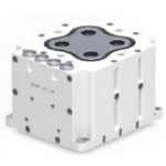
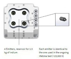
Enpulsion IFM Micro Thruster Micro 100
- Dynamic Thrust Range: 75 μN – 1.5 mN
- Nominal Thrust: 1 mN
- Specific Impulse: 1,500 – 6,000 s
- Propellant Mass: 1.3 kg
- Total Impulse: > 50 kNs
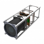
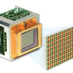
Payload – Imager (Camera)
This camera will give us Spatial resolution @ 30 km ~ 30 cm (12 inches) GSD for Panchromatic pictures on the Moon.
The Chameleon is a compact CubeSat imager that provides:
- High resolution Multispectral or Hyperspectral line scan imaging or
- High framerate RGB Bayer-pattern imaging
- Large integrated high-speed data storage
- Compact form factor that is optimized for integration with 3U or larger CubeSat frames
The Chameleon imager takes advantage of the space-qualified electronics of the Gecko imager and combines this with high-performance optics to maximize imaging capability in small form factor CubeSats. High capacity, high-performance mass storage is integrated into the compact design. The opto-mechanics have been optimized to fit within the available volume of CubeSat deployers thus providing maximum volume to accommodate the functionality required for your high-performance CubeSat mission.
Images are captured directly to the integrated mass storage. No need for additional payload data storage capacity on the satellite. Data can be streamed directly to a transmitter or to an onboard computer as required. Reliable operation is achieved by using a combination of proprietary hardware and ruggedized optics.
- Compatible with 3U and larger CubeSat standards
- VIS-NIR spectral range configurable as
- High frame rate RGB Matrix imager or
- Multispectral line scanning imager or
- Hyperspectral line scanning imager
- Large integrated high-speed data storage
- Spatial Resolution @ 500km: 9.6m
- Swath @ 500km 32 km
- Spectral Bands Multispectral: PAN + up to 10 VIS-NIR bands
- or RGB Bayer matrix
- or150 Hyperspectral bands
- Integrated mass storage Up to 160 GB
- Power consumption:
- during readout mode < 2.5 W
- during imaging mode < 3.5W
- 2U form factor (200mm x 94mm x 94mm)
- 1.35 kg
- 8-bit or 10-bit raw image output
- Full frame data as: Raw, Lossless JPEG2000, or thumbnail
- LVDS, SPI, I2C data interfaces (LVDS output rate from 1 to 240 Mbps)
- CAN data interface (requires optional add-on daughterboard)
- 5 VDC power interface (or 28 VDC with optional add-on daughterboard)
- Operating Temperature +10°C to +30°C
- Survival temperature -20°C to +70°C
- Radiation-tested to TID of 20 krad

Optional Upgrades
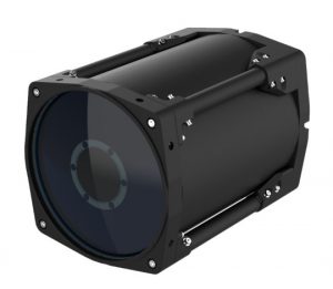
Imager TriScape100
This camera will give us Spatial resolution @ 30 km ~ 14 cm (6 inches) GSD for Panchromatic pictures on the Moon.
• 4.75 m GSD (at 500 km orbit height)
• A swath of 19.4 km across-track and 14.6 km along-track (at 500 km orbit height)
• Integrated RGB Bayer filter in the visible spectral range
• 128 Gigabyte non-volatile storage capacity for up to 8700 image frames
• On-board image processing and compression capabilities (optional)
• Comprehensive onboard telemetry and health monitoring

Imager TriScape200
This camera will give us Spatial resolution @ 30 km ~ 5 cm (2 inches) GSD for Panchromatic pictures on the Moon.
- 1.50 m GSD at 500 km orbit height
- 14.0 km swath at 500 km orbit height
- 7 bands in the VNIR spectrum
- 450 – 900 nm spectral range
- 9344 pixels in the cross-track
180° front and back facing camera
We are in the process of sourcing the best supplier.
Thermal IR camera
We are in the process of sourcing the best supplier.
